
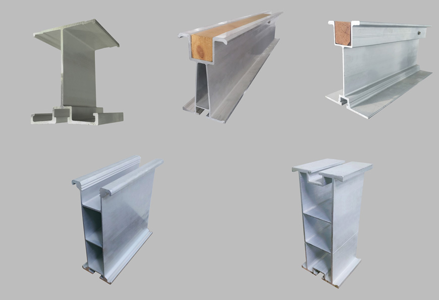
Longitudinal 10x10cm square wood is set up on the supporting beam and nailed firmly. Large bamboo plywood with size of 2440x1220x16mm is nailed on the square wood. The formwork must be attached closely to the square wood, and the bottom longitudinal slope and height of the beam are accurately set by adjusting the square wood.
To ensure the cleanliness of the formwork before concrete pouring, reserved holes with a size of 0.3m*0.3m are used as cleaning ports on both sides of the head. After the formwork is cleaned before pouring, it is sealed.
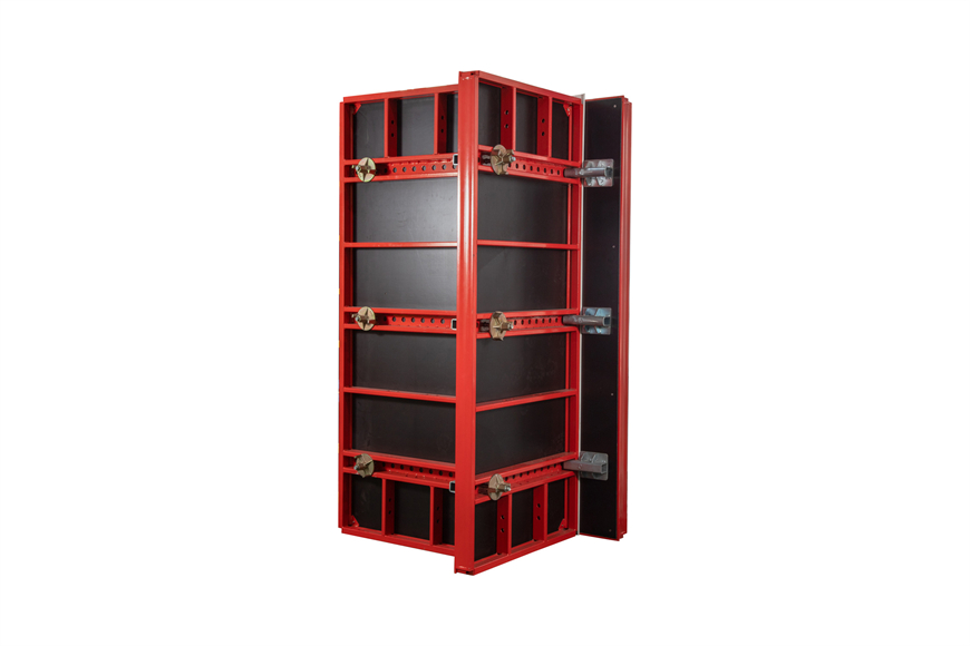
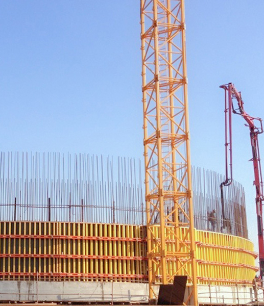
The side formwork adopts large and smooth bamboo plywood. The outer lining is made of back-to-back double-row steel pipes with 3 rows of pull rods. The φ20 pull rods are used to pull it together with the inner formwork. The longitudinal distance between the pulling bars is 0.9m and the vertical distance is 0.6m.
The head formwork, including adjustable formwork or other types of formwork systems, also uses bamboo plywood nailed with square wood as the formwork, which is cut according to the section size due to the presence of reinforcing bars and prestressed pipeline holes. The holes must be cut accurately according to the position of the reinforcing bars and prestressed pipeline. The size and position of the prestressed tensioning end groove template must be accurate.
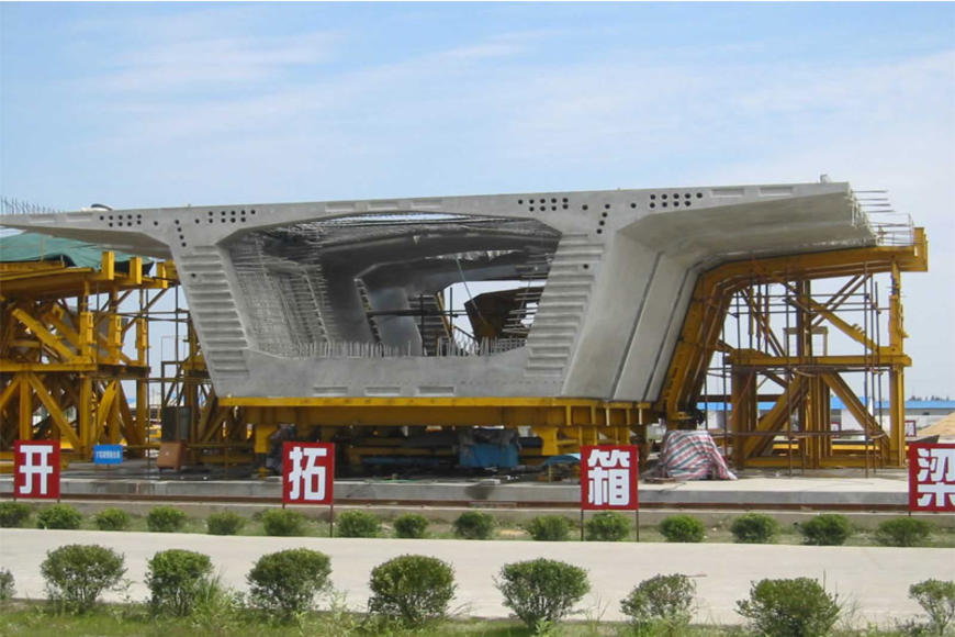
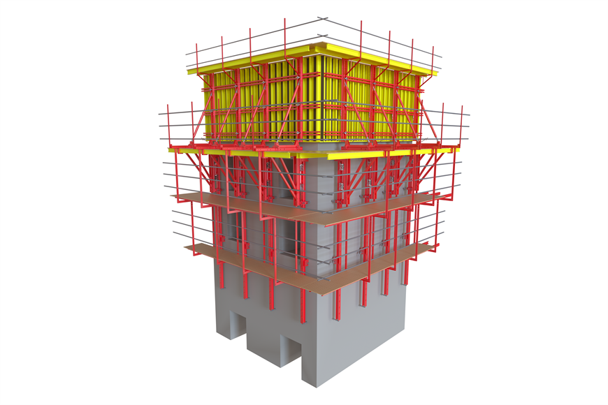
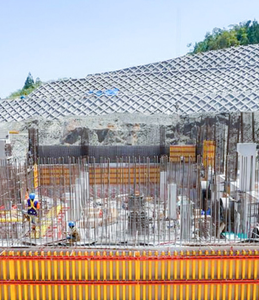
After the bottom and belly plate reinforcement and prestressing channel construction are completed, the box girder internal formwork is installed. The internal formwork is made of 16mm bamboo plywood. The box girder internal formwork support adopts φ48x3.5 foot pipe as the shelf, the column support is on the groove steel on the top surface of the bottom formwork, and a row is set along the bridge direction every 0.9 meters with 7 pipes in each row. Each row needs to be equipped with scissors braces and longitudinal and horizontal horizontal braces to increase the overall stability of the support and prevent the internal formwork from bulging. The internal formwork is equipped with 3 rows of pull rods, and the middle 20 pull rods are used to pull it together with the outer formwork. The longitudinal distance between the pull bars is 0.9m and the vertical distance is 0.6m. The columns cannot be supported directly on the top of the bottom formwork, and concrete pads must be used for isolation between them.
After the assembly of the bottom formwork and outer formwork is completed, the support is preloaded:
The purpose of the support preloading is to check the overall stability of the support, test whether the strength and stiffness of the support meet the requirements, and ensure construction safety. It also eliminates the influence of the non-elastic deformation of the foundation and support and determines the elastic deformation of the support.
The preload load is 120% of the weight of the beam. This plan uses sandbag heavy pressure method for the preload. The volume of the designed beam is 1458.66m3, and the weight of reinforced concrete is calculated as 2.6t/m3, so the weight of the beam is 3792.52t. When preloading, consider preloading according to the weight of the beam multiplied by the safety factor of 1.2.
The loading sequence of the sandbags should simulate the sequence of beam construction as much as possible. First stack the bottom plate, then the belly plate, and then the top plate and flange plate. The loading is carried out in stages. Since most of the weight is located in the bottom and belly plate positions, the middle part of the bottom plate, belly plate, and top plate are considered to be uniformly loaded on the bottom plate.
After the loading is completed, it should be observed under load for 24 hours, observed every 4 hours, and records should be kept. When the support is stable (the deformation of the support under load for 24 hours is ≤2mm), it is unloaded and unloaded according to the loading reverse order in stages.
With the professional R&D team and experienced technical team members from our formwork company, we will provide you with assistance on site when necessary, and you can rest assured that our solutions are always cost-effective. From the first contact to the completion of construction, we will always be there to support you. Welcome to inquire.
 Projects
 Coal Storage
 Metro Station
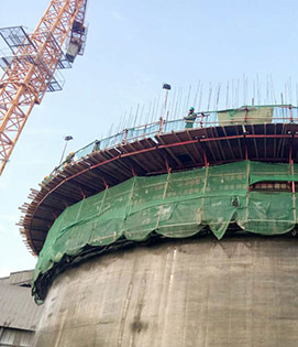
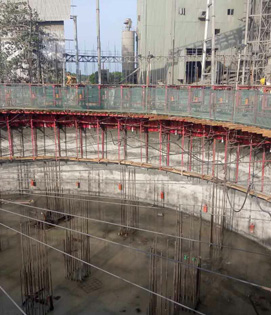 Silo Tank
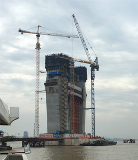 Shanghai Yangtze Bridge
 Dam
Dam
 Subway
 Silo Tank
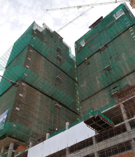
 ITC Colombo One Hotel & Residences
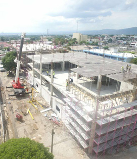
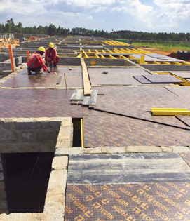
 Slab Flex 20 Formwork, Guatemala
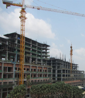
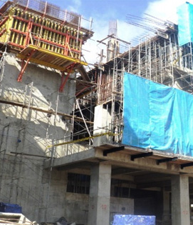 National Immigration Office
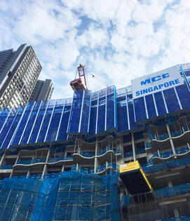 Queens Peak
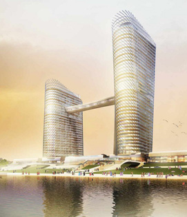
 Diamond Twin Tower
 Olympia City
 Jamaica Shopping Center
 Jinying Shopping Center
 Sheraton Apple One
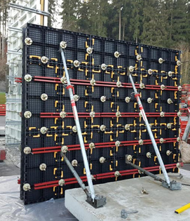 Bearing Capacity Test, Germany
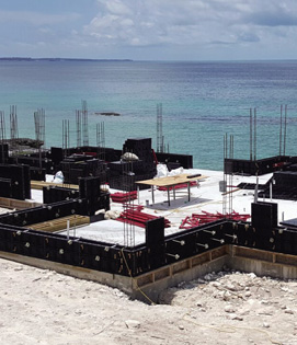 Sea Shore Villa
 Housing Project
 Apartment
 Housing in Mauritius
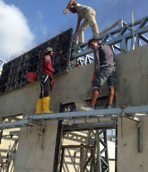
 Housing in Philippines
 Housing in UAE
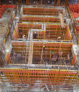
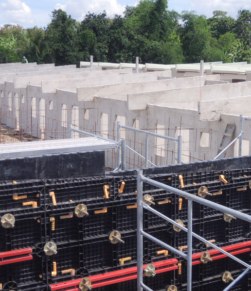
 Residential & Commercial Formwork
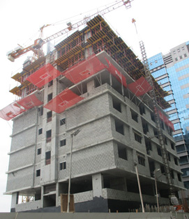
 High Rise Formwork
 Modular Houses
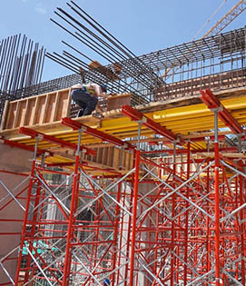
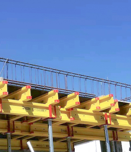
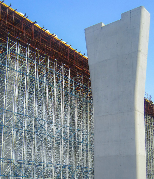
 Bridge Formwork
 Dam Formwork
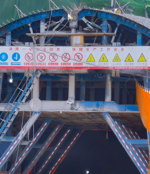 Tunnel Formwork
 LNG & Water Tank Formwork
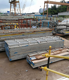
 Scaffolding Solutions


